TRIGA® Products and Technologies

Engineering What Endures – From TRIGA® to Tomorrow
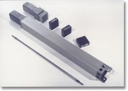
Control Rod Drive
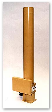 The TRIGA® Control Rod Drive for research reactors is an electrically driven linear drive mechanism to position and control movement of the reactor control rods and control blades.
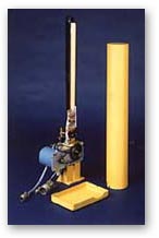 The Control Rod Drive Mechanism is an electric-stepping, motor-actuated linear drive equipped with a magnetic coupler and a positive feedback potentiometer. A five-phase stepping motor drives a pinion gear and a 10-turn potentiometer via a chain and pulley gear mechanism. The pinion gear engages a rack attached to the draw tube, housing an electromagnet attached to the lower end. The electromagnet in turn engages an iron armature, which is attached to a connecting rod assembly, which terminates at its lower end in the control rod itself. The electromagnet, armature and the upper portion of the connecting rod are all housed in a tubular barrel that extends below the water line in the reactor pool. The upper portion of this barrel is ventilated to permit unrestricted rod movement in water, whereas the lower portion has graded vent holes to restrict movement and to provide a damping action when the electromagnet is deenergized and the control rod is released from the drive.
A series of microswitches on the drive assembly controls the up-down movement of the control rod and rod drive. Rod up/down motion is controlled from the control console. In the event of a reactor scram, the magnet is deenergized and the armature will be released. The control rod will then drop, reinserting the neutron poison into the reactor core.
The control rod drive speed is adjustable over a wide range, and its design can accommodate control rods in lengths of 15, 24, 30 or 36 inches.
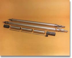
Fuels
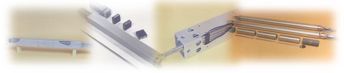
Low-enriched, long-lifetime uranium zirconium hydride (UZrH) fuel is the fundamental feature of the TRIGA® family of reactors that accounts for its widely recognized safety, rugged, dependable performance, economy of operation, and its acceptance worldwide. The large prompt negative temperature coefficient of reactivity characteristic of UZrH fuel results in safety margins far above those achieved by any other research reactor fuel. Large reactivity insertions are readily accommodated and are routine operation for some applications. Inadvertent reactivity insertions have been demonstrated to produce no fuel damage in TRIGA cores. Power coast-down from full power after loss of forced flow cooling (and resultant power scram) has been demonstrated to be a very benign event with the reactor immediately available to return to full power.
 Long core life of the TRIGA fuel results from the fact that a large amount of uranium can be readily accommodated in the fuel matrix, occupying a relatively small volume % of the mixture. Major operating cost as well as total fuel cycle cost savings result from the much longer core lifetimes resulting from the higher U loading in TRIGA fuels compared to competing fuels. The long fuel cycle times for UZrH fuel also result in the greatest possible operational flexibility for the system in that reactor shutdowns can most always be determined by user requirements rather than fuel cycle requirements.
The UZrH material also has fission product retention capabilities far superior to competing research reactor fuel. Aluminum clad plate type fuel melts at about 650°C, releasing essentially 100% of the volatile fission products. At this same temperature UZrH retains about 99.9% of these fission products even with the rugged clad removed.
 Fuel design options include low density LEU fuels containing 8.5 wt% of uranium, to high density fuels containing 45 wt% uranium with burnable poisons. Single fuel elements of 38-mm diameter are supplied for use in standard TRIGA Mark I and Mark II reactor core configurations. Smaller diameter fuels are used in fuel cluster configurations of four, 16 or 25 fuel rods for conversion of existing reactors to TRIGA core grids and higher power applications.
TRIGA fuel has been fully qualified by extensive testing under the U.S. Department of Energy’s Reduced Enrichment for Research and Test Reactors (RERTR) program.
Nuclear Instrumentation
NLW-1000
The NLW-1000 wide-range logarithmic channel combines the functions of logarithmic counting and logarithmic current conversion to provide a continuous indication of reactor power from source level to full power. A remotely located pre-amplifier minimizes EMI and other sources of interference and adjustable discriminator and gain controls allow flexibility in channel calibration with existing detectors. A differentiator circuit provides continuous indication of rate of change of power, and self test functions can check count rate, current, period and high voltage. Provision is made for permissive operation by computer of all test functions.
NMP-1000
The NMP-1000 is a wide range, linear current mode module with range switching. Ranges may be selected either manually or automatically, locally or remotely. Full scale sensitivities from 1 x 10-11 to 1 x 10⁻³ A are provided with indication of percent power on a front panel display as well as a front panel indication of each decade range. Compensation voltage as well as adjustable high voltage power supplies are provided in the module to allow operation with most existing current mode detectors.
NP-1000 and NPP-1000
The NP-1000 and NPP-1000 are advanced design neutron monitoring safety channels already in use at many research reactor installations worldwide. All NP-1000 channels feature current mode analog circuitry for percent power and pulse power monitoring (NPP-1000 only) using signals generated by an ionization chamber. They include a built-in pulse integrator circuit (NPP only) and connect to computer analysis systems and/or hard-wired scram systems. The integrity of NP-1000 output signals is assured by the use of isolation devices.
NFT-1000
The NFT-1000 fuel temperature monitoring channel converts millivolt signals from thermocouples into a usable signal level for monitoring and display. It includes a dual trip unit, a calibrator module to test the channel trip functions as well as provide a fixed calibration point for verifying the correct operation of the unit, and an isolated transmitter module to drive external indicating-recording devices. The NFT-1000 is designed to be physically similar to the other modules in the line of analog instrumentation modules.
Complete Control Systems
All types of research reactors can be operated with this multipurpose control and instrumentation system. A state-of-the-art instrumentation and control system using microprocessor technology provides replacement of older, existing instrumentation and control systems that contain obsolete components. Our features include:
- Eliminates most manual data logging
- Provides automatic or manual reactor operation modes
- Provides complete real-time operator display
- Replays historical operating data on monitor or printer
- Meets all applicable NRC and IEE specifications
Here's How Our System Works
The complete system consists of three major subsystems:
- Control Rod Drive and Detector System
- Data Acquisition and Signal Processing System
- Control Console System
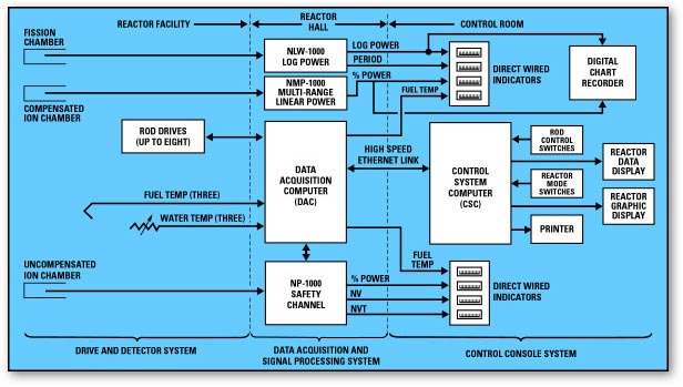
The Data Acquisition and Signal Processing System and Control Console System each have independent computers (DAC and CSC) for monitoring and control purposes. The Data Acquisition and Signal Processing System may include the NLW-1000 and NMP-1000 nuclear instruments and the related reactor safety scram and shutdown circuits. 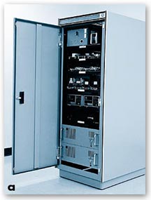 All these systems are mounted in an auxiliary instrumentation cabinet, which is located in the reactor hall, usually near the reactor. Thus, even if the Control Console System is disconnected, the Data Acquisition and Signal Processing System can control or shutdown the reactor in a safe manner.
Information on all aspects of reactor operation is displayed on the Control Console System. The two-color graphics monitors can display real-time operations data in concise, accurate and easily understood formats. Bar graph indicators and visual and audible annunciators are also provided. Information displayed on the two monitors can be recorded on hard copy using the graphics printer in the Control Console System. The DAC collects data during reactor operations and stores it in a historical database. Reactor operations can then be replayed in real-time or slow motion. This record is a powerful tool that can be used for operations review and maintenance troubleshooting.
Reactor control rod position commands are transmitted via a high-speed Ethernet link from the Control Console System to the Data Acquisition and Signal Processing System and in turn to the rod drive mechanisms. This reduces the complexity, vulnerability, and cost of data transfer. The Data Acquisition and Signal Processing System computer controls rod positions using integral software during automatic mode operation.
Safety Features
The two independent, redundant percent power safety instruments are provided to ensure safe operation of the reactor. Both instruments are designed to meet all applicable specifications and both instruments also have automatic pre-startup on-line self-diagnostic/testing and calibration verification with data display and documentation printout. Both instruments also have isolated outputs for display and safety scram circuit inputs. Redundancy and diverse designs ensure against reactor instrumentation and control system common mode failure. Backup bar graph displays and safety/scram circuits are also hardwired to instrument outputs.
Data Display and Storage
Two color monitors provide real-time information: one shows reactor operations graphics and the other displays important operating parameters. Hard copies of the two displays can be made using the graphics printer.