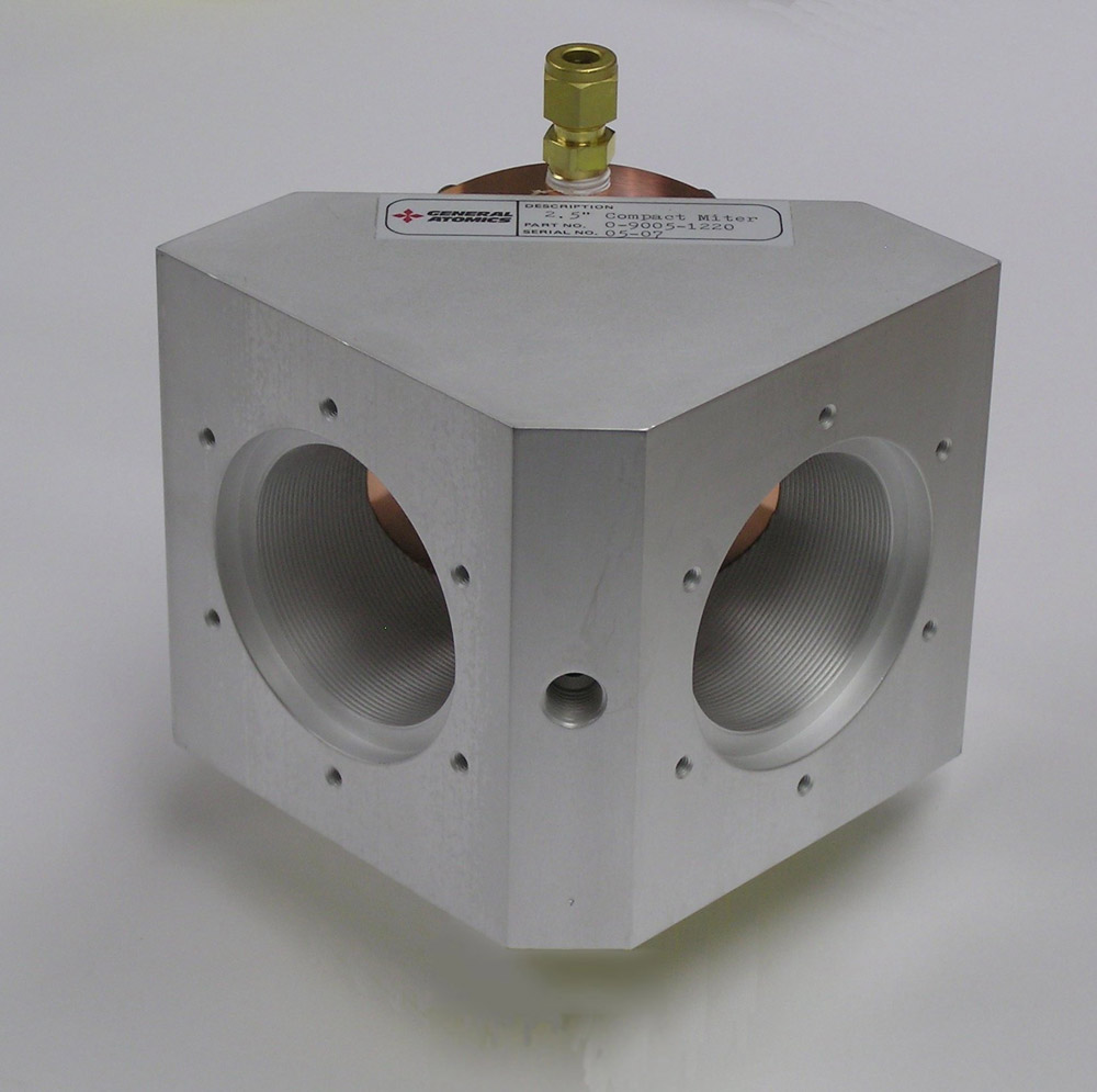
Miter Bends

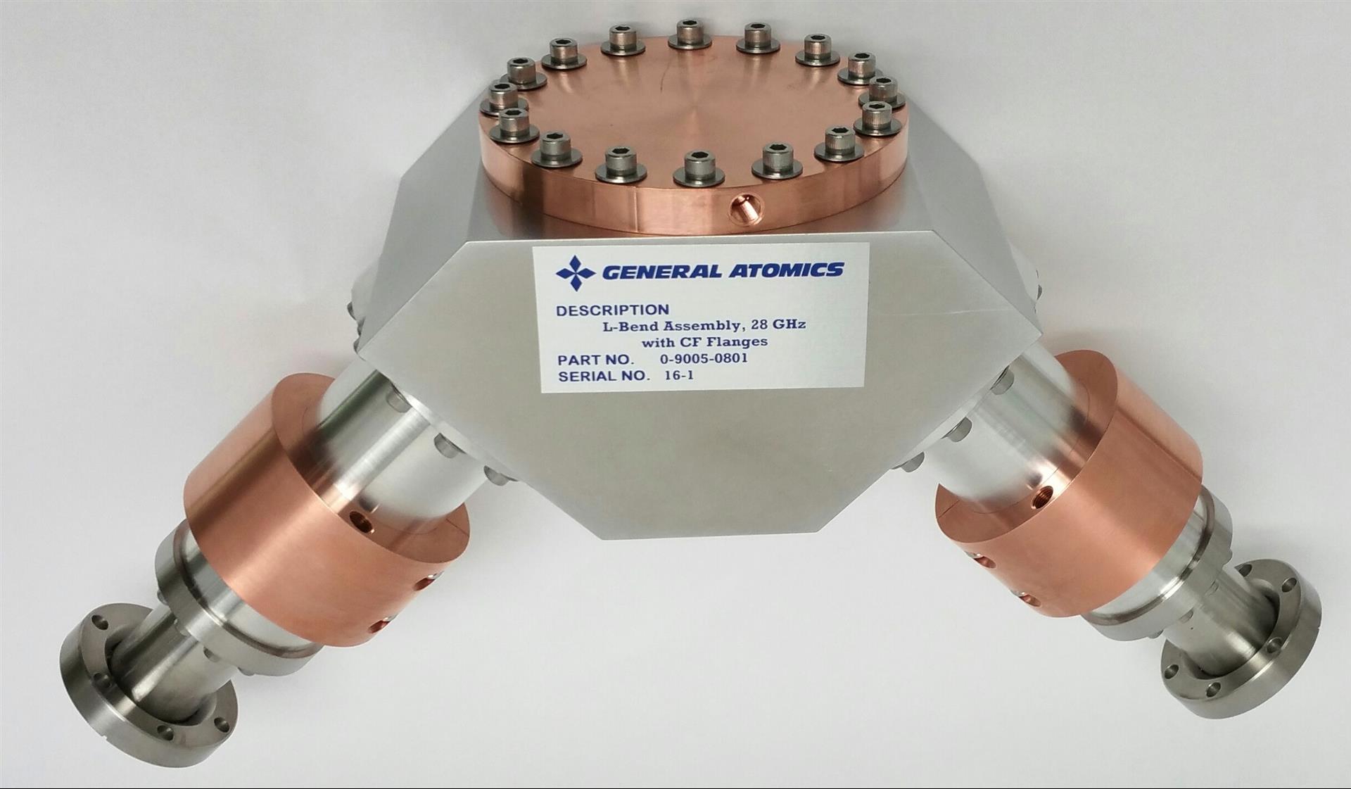
  • General Atomics can supply miter bends for use with any of the corrugated waveguide sizes.

  • The theoretical mode conversion losses in HE11 miter bends vary approximately as the 1.5 power of the ratio of the wavelength to the waveguide diameter. For example, the approximate mode conversion loss in a 31.75 mm waveguide miter bend at 110 GHz is 1.4%, and in a 63.5 mm waveguide at 170 GHz this loss is approximately 0.26%.
Non-vacuum miter bends are made with corrugated waveguides machined into a block
Non-vacuum miter bends are made with corrugated waveguides machined into a block. Recesses are also machined into the block to accept mating waveguides with good alignment. The mirror is bolted into the block.
Vacuum miter bends have corrugated waveguide arms machined in one piece
Vacuum miter bends have corrugated waveguide arms machined in one piece with the miter block. Aside from the seals needed to connect ordinary waveguides to the ends, the only vacuum seal required with a simple miter bend is a Helicoflex® metal seal under the mirror. This photo shows a vacuum miter bend in 63.5 mm waveguide with a power monitoring feature. Miter bends can also be supplied with fiber optic arc detectors and with ports for vacuum gauges.

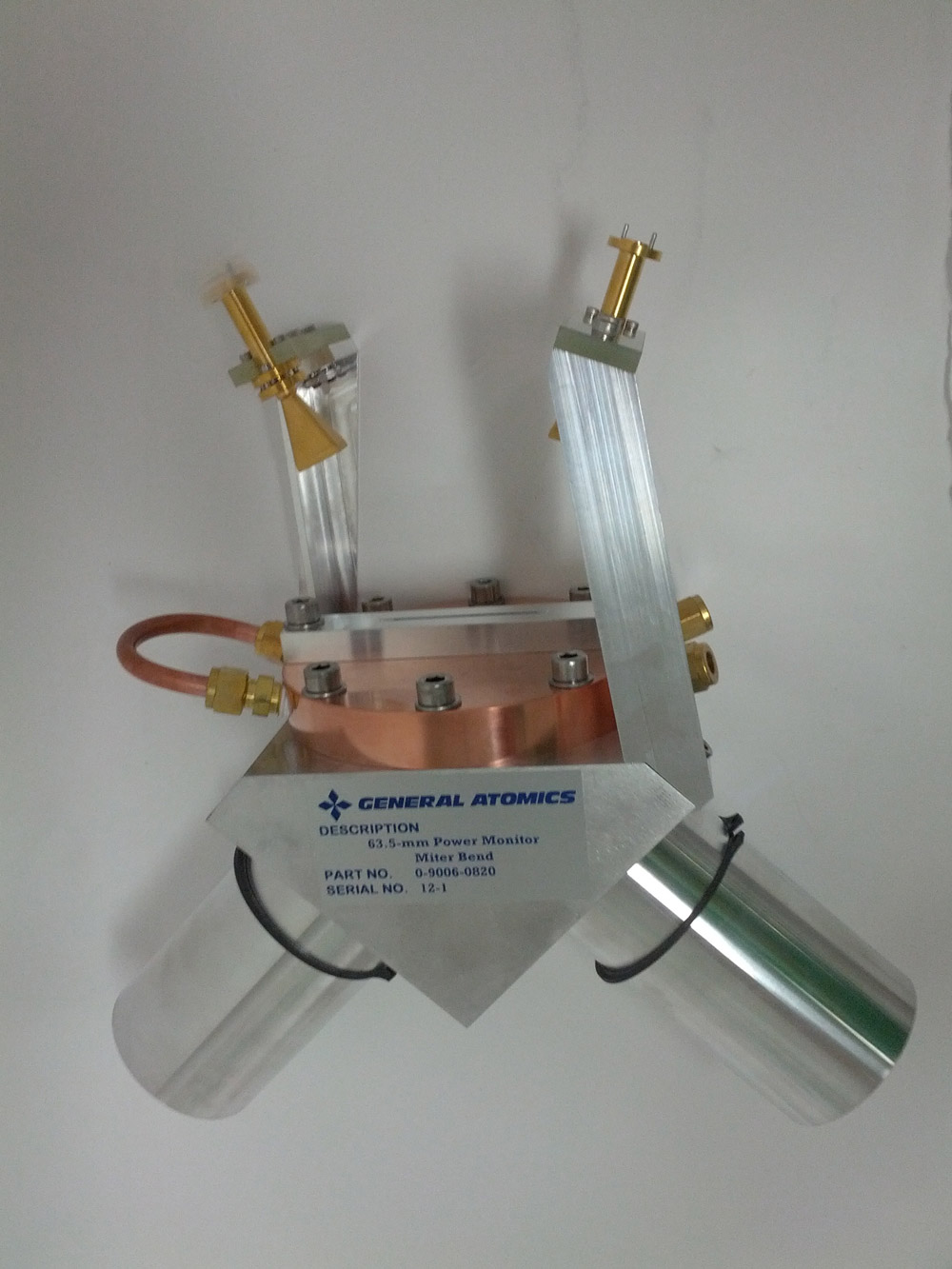
Extremely low loss miter bends utilizing external mode converters to minimize the diffraction loss at the mirror region are also available. Low-loss miter bends for the TE01 mode as well as the HE11 mode have been made with this technique.

Low-loss TE 01  miter bend for 32.6-mm smooth waveguide at 28 GHz.
Low-loss TE 01 miter bend for 32.6-mm smooth waveguide at 28 GHz.


Contact
James Anderson
Head of RF Technology, MFE Division
andersonjp@fusion.gat.com

Zabrina Johal
Senior Director of Strategic Development
Zabrina.Johal@ga.com